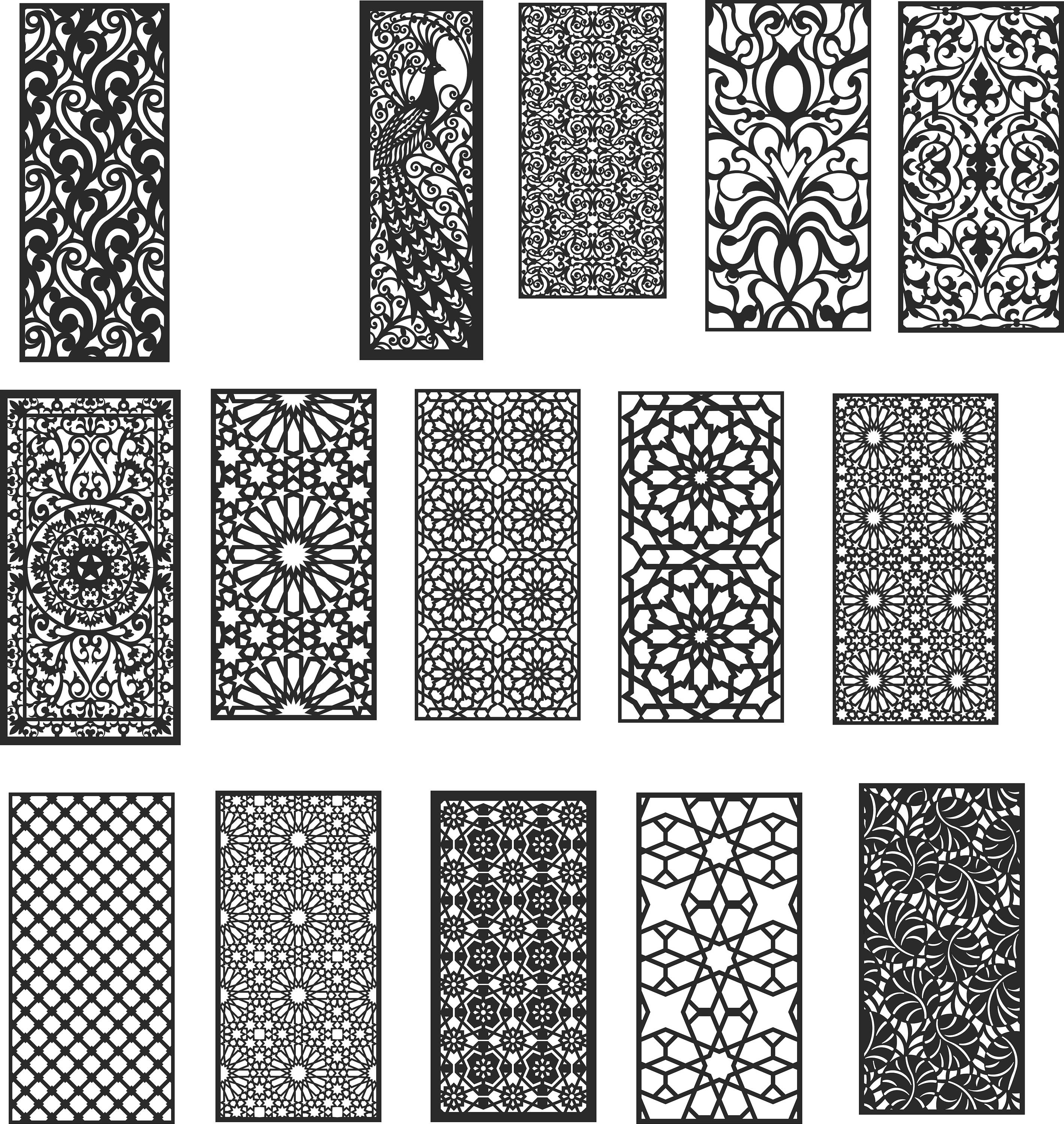
When you want to create a 2D design to be cut using a CNC router or 3D mill there are a few few things you should know before you start.
Your Idea → CAD → CAM → Controller → Finished Object
To get the idea inside your head to become a physical reality through the use of CNC technology you must first know what software systems to use.
CAD (Computer Aided Design or Drafting) Systems, create either vector based graphics to depict the objects of traditional drafting, or may also produce raster graphics showing the overall appearance of designed objects. For cutting in 2D be sure to create vector drawings. Use these systems to create and edit your project until it is finished, but the computer doesn’t know what to do with this information yet. Next export the file as an AI, EPS, DXF, or PDF to the next software system.
This site holds silhoutte CNC DXF art files for shapes that one can cut on a CNC machine. The DXF shape art files are 2D outlines. I have been cutting the shapes on my home built CNC hot-wire foam cutting machine. Download the shapes for FREE! Jan 3, 2021 - Unique DXF Plasma Laser File designs from one of a kind DXF Art files, Free DXF Files to 3 dimensional cut and assemble DXF designs, like firepits.
Some CAD systems are:
- Adobe Illustrator
- Inkscape
- AutoCAD
- Corel Draw
Advice → It’s good to know when creating 2D files in CAD systems that the software you will be sending this file to, CAM systems, do not like open shapes. An Open Vector is a series of lines, or Paths, that are aligned or layered over each other to look like shapes but are really not Joined. This is important know because the CAM system attempts to create toolpaths using the vectors as guides and if the vectors are not joined then the computer reads each line by itself creating a toolpath that is infinite. I will discuss tool paths soon.
How to know whether your shaped is joined – In Adobe Illustrator hold the cursor over different parts of the shape, if each line is selected separately then your vectors are not joined. If so then use the Group Selection Tool under the Direct Selection Tool – tool menu to select the each line then type CTRL+J or CMD+J. Conversely if you hold the cursor over one line and the entire shape is selected then you have a closed vector.
CAM (Computer Aided Manufacturing), these software systems reinterpret the vector, or 3D data, from the CAD systems to create coded instructions machines use to maneuver cutting tools . The term for these files are Toolpaths meaning they are creating a path the tool will follow. The code the tool path is made from is called G-Code; represented as the letter G followed by an instruction number and an X and Y coordinate: G1 X42.0435 Y51.009. A (Z) coordinate is added to files that are 3D. You probably will never see the G-code being created because this is happening behind the scenes.
We use Vectric’s Cut2D and Cut3D CAM System at the IMRC Labs.
Cut2D
- Automatically converts CAD drawings and Graphic designs to GCode / CNC Toolpaths.

- Opens most industry standard 2D vector drawing formats DXF, EPS, AI & PDF file formats.

- Pocket Machining with either raster or offset machining patterns, plus the option to ramp the cutter into the material.

- Profile Machining-running the cutter around the outside, inside or on the selected geometry, with the option to ramp the cutter into the material.
- Automatic cutter diameter compensation for toolpaths ensures parts are cut to the required size. Simply select the shapes and Cut2D compensates for the cutter diameter and shape.
- Interactive Tab / Bridge placement to ensure parts are securely held in place when cutting from sheet material.
- Automatic calculation for Outside and Inside cutting when multiple shapes are selected.

- The option to Ramp the cutter into the job is very important when cutting hard materials because it reduces the load on the bottom of the cutter.
- 3D Colour and 2D wireframe toolpaths Previews shows exactly what the part will look like when machined.
Vectric.com, 2013
Cut3D
- Cut3D quickly and easily converts 3D models into CNC toolpaths (3D XYZ point data) that can be machined on conventional 3 axis CNC machines.
- You can use this software for the following 3D Models, Rapid prototyping, Sign Making, Wood Carving, Statues, Jewelry, Engraving, Stone cutting, CNC routing, Milling, Custom fireplaces, Door panels, Earrings, Memorials, Commemorative plaques
- Automatically converts STL, 3D DXF, 3DS, OBJ, WRL, LWO, V3M file formats.
- Choose to create 3D objsects using three different methods – Single 3 axis machining – 2 sided Top and Bottom machining – 4 sided Top, Bottom, Front and Back machining.
- 3d Models that are to large / thick for the material or machine gantry height can easily be sliced into separate models. Toolpaths for each model slice can then be calculated and saved ready for machining. The machined slices can be assembled to make the complete object.
- Fast and efficient Z Level rough machining removes unwanted stock material quickly and easily, leaving material on the model for the Finishing toolpath to remove.
Vectric.com, 2013
In these two CAM software systems you will set the dimensions of the material to be cut, deciding what tools you will use to cut with and saving the toolpath information in the correct file format. example – tutorial.tap
Controller Software – is where the rubber meets the road so to speak. After creating a design in CAD and toolpaths in CAM it’s time to send the file to the software that controls the machine. This software (we use WinCNC) turns the G-code instructions of the tool path into physical movement by controlling the motors on the machine. There is a motor for each axis X, Y, and Z. Once the the material you want to cut is placed on the table, the start point is set, and it’s time to run the file.
This is the most technical part of the process, the controller software is designed by engineers and it is not user friendly. Many times you will have to type commands into a field then press enter to command the machine to do a function. Please read the manual carefully before trying any operations with the machine. The software causes physical movement and any errors could break the machine or hurt someone.
The purpose of this article is to outline the process of the CNC work flow, in basic terms, and to inform you of somethings that need to be thought of before you start creating any complex design. I don’t want you to come to a shop tech with a file full of open vectors and think you’ll be able to cut the part before the looming deadline. If you have any questions feel free to comment below.
Description
Description:
222 CNC Vector DXF + CDR Art file ready to cut for plasma router laser – Laser Cut Vector Templates , Decorative Cutting Templates , DXF Cutout Digital Stencils , Geometric Pattern Panel Templates , Room Divider , Screens , Wall decor , Vector Digital Files to use for your crafting projects , Woodworking , Laser Cut , CNC , etc.
Terms of Use:
– 2d modelcan only be usedfor the manufacture ofproductson CNC machines;
– 2d modelyou can notresell,exchange or transferto third parties.